| Scott's Atlas / Craftsman 101.07403 12x36" Lathe, modifications and projects. Stone Mountain, GA | Unique Visitors: |
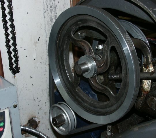 |
The double pulley on the counter shaft is on backwards as it lines up with the motor pulley better. The motor only has a sigle pulley anyway. The VFD allows me to have the same range as the double pulley by just turning the speed knob on the VFD. The countershaft pulley was way out of wack. I spent a lot of time correcting its problems. Its rework is described in the "Zamak pulley repair" page. It works great; I can use a speed from 30Hz to 90Hz for about 700 to 1740 RPM. The VFD will do 0.5 to 200Hz but this motor is not designed for that type of frequencies. I have tried it as low as 20Hz and up to 120Hz and it ran fine, just don't want to stress it in any way. The VFD is only for 1/2HP or 0.4 KW. It works fine with a 1HP motor as the lathe only needs about 1/3HP. I do see it has a relatively high no-load current a bit over what is stated on the motor. I have a 5A fuse on the 110V in and it has not blown. At 20Hz, I get 11 RPM with the back gear. With the highest speed and pulley settings, I get about 1100 RPM. The VFD was temporarily mounted for tests until an enclosure was found. |
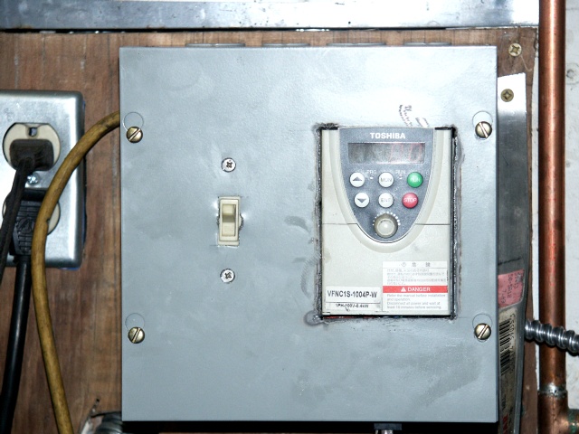 |
The VFD and much of the wiring was mounted in an enclosure. Just an inexpensive 8x8x6" junction box. It has an on/off switch, a fuse, a small fan and a relay to control the VFD. A small transfomer powers the relay, fan and lights in the switches. The VFD takes just 3 wires to control remotely, forward, reverse and common. The front panel of the VFD could be used, but reversing has to be done though the setup menu. The control panel connects via a RJ45 connector on the bottom of the box. The fuse is internal; a panal mount fuse will be added later. |
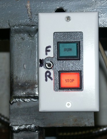 |
On the lathe, I made a control panel with two lighted switches. Since these are momentary, I needed a relay to latch the run/stop signals. The small switch on the left has Forward/Off/Reverse positions. |
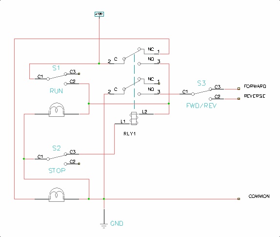 |
The control panel schematic is shown on the left. The VFD has 3 control lines used Forward, Reverse and Common. Shorting Forward to Common will cause the motor to run foward as long as the lines are shorted. Similarly, Reverse will run reverse when shorted to common. The Forward and Reverse lines are very low current, on the order of 1 milliamp. S1 and S2 are the RUN and STOP switches shown above. Pressing S1 will energize the relay. One pole of the relay also is in parallel with S1. So once S1 is pressed, the relay will stay on as long as ther is power. S2 is stop. It just breaks the current to the relay. The pole of the relay that is in parallel with S1 also powers the light bulbs in the switches. The second pole of the relay is fed through the FWD/REV switch to feed the switch closure to the selected VFD pin. |
|
The player will show in this paragraph
|
Here's a video of the VFD running at 2.4Hz. That gives about 1 RPM with the back gear. It can go as low as 0.5Hz or about 1/5th RPM. If you can not see the WMV video on the left, you can download it here. |